Wanting to interface my FlySky FS-iA6B RC receiver with the ESP32 in my robot I quickly found the IBUSBM Arduino library. However there were a couple of issues that needed figuring out due to me wanting to use a single serial port instead of two.
IBUSBM references the betaflight wiki in regards to connecting the iBUS signals. And a forum thread on dronebotworkshop has a discussion how to do the communication over one serial port with level shifting. I did play around with the level shifting circuit proposed there, however in the end it turned out that I didn't actually need it as the FX-iA6B has 3V outputs.
Initially I used a cheap logic analyzer to verify that the data was being correctly combined. But I quickly realized that this was not giving me any information on the actual voltage levels of the signal. So once I was reasonably happy with the circuit I went and hooked it up to an oscilloscope to check them. This is when I realized the signal levels were 3V so I removed the level shifter and tried different variations of just diodes and resistors.
Once the servo and telemetry messages were combined into one port the messages were no longer getting parsed properly on the microcontroller side. This was due to some specific timing assumptions the library was doing that didn't work with combined messages. A valid response to some messages is to echo back the same message. But because the TX and RX share a single pin any messages sent out will also be received. This echo needs to ignored otherwise it just keeps going indefinitely. The library avoided this issue by assuming that no data would be received for at least 3ms after getting a valid message. It would discard any data in that period, thereby never parsing its own responses. This however broke the telemetry parsing since that data shows up approximately 0.8ms after the channel data block. I fixed this issue by keeping track of the number of bytes being sent out. This enables me to immediately read and discard those bytes to get rid of the TX -> RX echo. Additionally I changed the timeout code to only apply in specific cases when failing to parse properly and reduced it to 500us after the last data is parsed.
The library also sets itself up so that the processing loop is called every ms. While this works, now that we are reading more data this may not be fast enough. Having the read delayed by 1ms will affect how fast we can respond to a telemetry query message. It could also affect the timeout behavior, as data in the serial buffer will be parsed without any indication of how old it is. There should be no issue calling the loop function faster because if the serial buffer is empty it returns immediately. I removed the automatic loop code and just call the processing loop from the main program loop continuously.
These changes also allow me to easily use a ESP8266, if I wish, since it only has one hardware serial port.
Modified library files: IBusBM Files
Schematic
The original betaflight schematic was designed for a single pin, open drain, software UART connection. By adding an additional diode it also functions with a standard two pin UART, however this is not optimal.
My understanding of the schematic is that the diodes and resistors protect the I/O pins in the case where one is being driven high and the other is low. If the diodes are not present there may be a high current condition if one port is high and the other is low. The resistor provides similar protection by limiting the current to a maximum of about 3mA.

Betaflight schematic modified for standard UART. Not ideal but can be made to work.
Improved Schematic
We can improve the logic level voltages if we re-arrange the circuit slightly and add an additional diode and resistor. Additionally we can also change the diodes to Schottky diodes to reduce the voltage drop.

Improved iBUS signal combiner schematic.
The diodes I used are BAT43 Schottky diodes, standard 1N4148 signal diodes will also work with one minor caveat. The sensor response signal at the RX pin is then above the input spec of the ESP32. This is not critical since we discard that data anyway. However if we don't receive those bytes then we need to wait for the timeout to occur which slows down processing slightly.
The 100K resistor slightly improves the rising edge on the signal, it can be omitted but that leaves the RX floating. It also raises Sens-requ and lowers Sens-resp voltages by a negligible amount.
D2 blocks the servo data from the sensor iBUS and improves the low-level voltages. It also prevents the sensor iBUS from pulling up the Servo signal low level. Required if using 1N4148 diodes, acceptable without when using BAT43 diodes with a 2.2K resistor.
Betaflight recommends a resistance of 10K to 1K for the sensor iBUS resistor. But this only applies if you have a open drain IO. Since we don't, we need diode D3 and a lower resistance. If we do software serial instead of hardware serial we could reconfigure the TX and possibly get rid of the diode and increase the resistance.
Measurements
I did a whole matrix of different diodes and resistance values and chose the parts that gave the best measured low level voltages. High level voltages for every variation were always very close to 3.3V. Measurements are relatively accurate but I was just using the oscilloscopes on-screen cursors to get them.
The ESP32 input spec for low level voltages is -0.3V to 0.825V at 3.3VDD.
Measured low level voltages

Servo-data: Channel data from the RC receiver to the ESP
Sens-requ: Sensor request from the RC receiver to the ESP
Sens-resp: Sensor response from the ESP to the RC receiver

Sens-resp @ RX voltage level is non critical as this data is discarded.

Values in green are the variations with the better voltage levels.
Underlined values are above the ESP32's low level input specification.


1N4148, R5 1K                (Servo-data: 0.54V, Sens-requ: 0.64V, Sens-resp: 0.69V)  (1.07V Sens-resp @ RX)
1N4148, R5 1K, without D2    (Servo-data: 1.10V, Sens-requ: 0.14V, Sens-resp: 0.69V)  (0.57V Sens-resp @ RX)

1N4148, R5 2.2K              (Servo-data: 0.55V, Sens-requ: 0.75V, Sens-resp: 0.84V)  (1.05V Sens-resp @ RX)
1N4148, R5 2.2K, without D2  (Servo-data: 0.85V, Sens-requ: 0.25V, Sens-resp: 0.85V)  (0.55V Sens-resp @ RX)

1N4148, R5 4.7K              (Servo-data: 0.54V, Sens-requ: 0.96V, Sens-resp: 1.09V)
1N4148, R5 4.7K, without D2  (Servo-data: 0.75V, Sens-requ: 0.50V, Sens-resp: 1.09V)

1N4148, R5 10K               (Servo-data: 0.54V, Sens-requ: 1.37V, Sens-resp: 1.46V)
1N4148, R5 10K, without D2   (Servo-data: 0.65V, Sens-requ: 0.95V, Sens-resp: 1.46V)


BAT43, R5 1K                 (Servo-data: 0.25V, Sens-requ: 0.35V, Sens-resp: 0.40V)  (0.48V Sens-resp @ RX)
BAT43, R5 1K, without D2     (Servo-data: 0.80V, Sens-requ: 0.14V, Sens-resp: 0.40V)  (0.25V Sens-resp @ RX)

BAT43, R5 2.2K               (Servo-data: 0.24V, Sens-requ: 0.46V, Sens-resp: 0.55V)  (0.46 Sens-resp @ RX)
BAT43, R5 2.2K, without D2   (Servo-data: 0.55V, Sens-requ: 0.27V, Sens-resp: 0.55V)  (0.27V Sens-resp @ RX)
  One less diode but has servo -> sens connection due to that.

BAT43, R5 4.7K               (Servo-data: 0.25V, Sens-requ: 0.70V, Sens-resp: 0.83V)
BAT43, R5 4.7K, without D2   (Servo-data: 0.44V, Sens-requ: 0.50V, Sens-resp: 0.82V)

BAT43, R5 10K                (Servo-data: 0.25V, Sens-requ: 1.14V, Sens-resp: 1.25V)
BAT43, R5 10K, without D2    (Servo-data: 0.35V, Sens-requ: 0.95V, Sens-resp: 1.25V)
Prototype
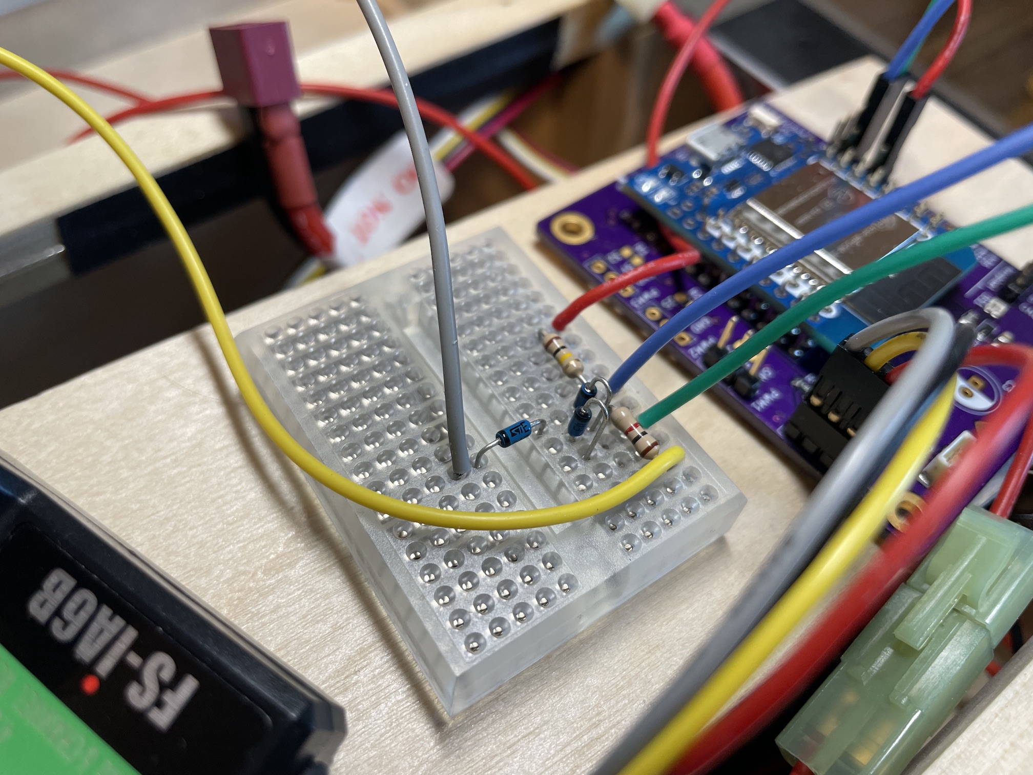
Breadboard prototype showing controller, signal combiner & RC receiver.